
Introduction
This article explains how to achieve a right service placement strategy and Service Fabric (SF) cluster capacity planning. I have written this post as a continuation of this previous article. Continuing the previous article allows me to extend the same contextual problem and find solutions.
According to the previous article, we should place WFE services in certain set of nodes exposed to LB and internal services in a different set of nodes which are not exposed to LB and optionally they may have access to the backdoor database infrastructure.
In fact what I have tried to achieve is a typical infrastructure setup with DMZ and non DMZ. The difference is I have used single SF cluster to hold the DMZ and non DMZ.
SF is such a powerful and a flexible platform that you can map many kinds of scenarios like this. In SF, we can achieve these logical splits using placement constraints. In its simplest form placement constraints work based on the properties we set to the nodes.
Node properties are key value pairs used to tag nodes. Through the application we then instruct SF to place certain services in certain nodes which satisfy the placement constraint rules.
Placement constraint is the logical composition of node properties which yields a Boolean value to the run time.
NodeProperty1 == "super" && NodeProperty2 == "nvidGPU"
SF will place the node which meets this criteria and place the service in that node. We decorate the node with these node properties and access them in the application and put placement constraints on services.
You can configure the node properties in Azure portal under the node types. If you’re running the on premise setup we can configure it in the ClusterConfig.json. Like any configuration, placement constraints can also be parameterized in the ApplicationManifest.xml using the corresponding parameters xml file. This article describes it very clearly.
Virtual Clusters
Let’s see how to setup the cluster. In a sample setup with 6 nodes and FD:UD = 6:6, the DMZ and non DMZ setup is made like below. Here DMZ has 2 nodes and non DMZ has 4 nodes.
FD : Fault Domain, UD : Update Domain
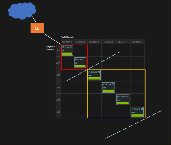
Nodes are marked with NodeType property ex or nex. WFE services have the placement constraint (NodeType == ex) and internal services have the placement constraint (NodeType == nex).
Node properties make the logical idea of DMZ. Infrastructure and network configuration will give the real separation. In this case we placed ex nodes and nex nodes in different networks and additionally configured a software firewall in between both subnets.
So this placement strategy creates two virtual clusters inside the real cluster. WFE services are placed in the DMZ (red box) and internal services are placed in non DMZ (yellow box).
Dive Deeper
The above virtual cluster setup creates some challenges in cluster planning. Example, though we have FD:UD = 6:6, by imposing the constraint, WFE services have a FD:UD = 2:2 cluster and internal services have a FD:UD = 4:4 cluster.
So overall cluster planning and how SF makes placement decisions are better be understood and simulated for a better understanding. Before diving, I highly recommend to read this article.
So we know, when setting the cluster we have to specify the FDs and UDs, in fact it is the most important step.
In the simplest form FD:UD ratio is a 1:1 setup. It serves majority of the scenarios.
I have played and with this 1:1 mode and I don’t think I will look into other ratios unless there’s a quirky requirement. Also, if you’re using the Azure cluster this is the default setup and I’m not sure whether you can change that. 😉
Though we can have any number of nodes in the cluster, placement of a service is decided by the availability of FD/UDs. Just increasing the number of nodes in the cluster will not result capacity increase.
First let’s look how SF places the services when there’s no placement constraints defined. The default placement approach SF is adaptive approach. It is a mix of two approaches known as Maximum Difference and Quorum Safe.
- Maximum difference is a highly safe placement approach where any replica of a single partition will not be placed in same FD/UD.
- Quorum safe approach is a minimal safety mode, it is chosen when specific conditions are met. Here SF tries to be economical of the node capacity. The replicas belong to a single partition and the quorum will be treated in maximum difference way and others may be placed in same FD/UD.
Instance / Replica : The term instance is used to refer the stateless service copies and replica is used to refer the stateful service copies but in this article I have used the term replica to refer both.
Quorum: A quorum in a stateless service is the number of requested (instance count) replicas, and a quorum in a stateful service is the number of requested minimum replica set size.
If you have read the recommended article, we can summarize the placement approach of SF with a simple pseudo code like below.
rs: replica size, fd : fault domain, ud: update domain n: number of nodes
if ( rs % fd == 0 && rs % ud == 0 && n <= (fd * ud) )
        return "quorum safe"
else
       return "maximum difference"
SF deciding an approach would not yield the successful placement. Because this is just a decision for the placement strategy, once the decision is made SF looks for available nodes which meet the placement criteria.
If there’s not enough nodes to place the services then SF will throw either an error / warning depending on the situation.
FD:UD = 1:1 Case with Virtual Cluster
The below table shows the cluster simulation. I created this Excel sheet to understand the cluster and added some functions to simulate the cluster. I have translated the high level logical decisions SF makes into simple Excel functions.
Download from : Cluster Visualization Excel

The first section of this report shows the scenario without any placement constraints. So the all FDs/UDs and all nodes are available to all the services.
Replica minimum is a must to have replica count of a partition of a Stateful service. Target replica is the desired number of replicas for the partition. Stateless services have the replica minimum equal to the target number of replicas, because there’s no such idea as minimum replica in Stateless services.
Observations
- Row #15 and #16 – Stateless service replica is greater than available FD/UD. Though they are different approaches the bottom line is that cluster does not have enough number of FD/UD. SF reports an ERROR.
- Row #9 – Stateful service minimum replica size is greater than available FD/UD. SF will report an ERROR. This is a very similar case like above.
- Row #10 – Stateful service minimum replica size is lower than available FD/UD but target replica size is higher. SF reports a WARNING.
- Row #16 – Stateless service replica is greater than available FD/UD. It’s obvious increasing the number of nodes doesn’t make any sense and SF will not use them as long the FD/UD is not expanded. In Row #17 the same scale is achieved with the optimal setup.
- Row #22 and #23 – looks same but they have different approaches. Both run in the warning state because both approaches have met the minimum replica size but not the target replica size.
Second section has the cluster implementation with the placement constraints. So the report is filled with FD:UD 2:2 in ex and FD:UD = 4:4 in nex. Visualizing them as two difference clusters.
Summary
Here I’ve summarized things for quick decision making.
Rule #1: In stateless services replicas CANNOT scale more than the number of valid fault domains in the cluster. Trying so will cause error.
Rule #2: In stateful services configured minimum (this cannot be lower than 3) replica count of a partition CANNOT scale more than the number of valid fault domains in the cluster. Trying so will cause error.
Rule #3: Whenever possible SF tries to be economical in its placement decision not using all nodes. Consider Row #18 and #19, here in #19 the SF has 4 nodes in four different FD/UD but still decides Quorum Safe.
Like the static node properties there can be dynamic node properties which are also considered in decision making and influences the available FD/UD. In this article I haven’t covered those cases.
In fact if we’re to summarize the ultimatum
If you’re to scale your service (regardless of stateless or stateful) to x number of copies then you should have minimum x number FDs satisfying all specified placement constraints of that service.
It sounds very analogous to a typical stateless web application scale out. 😉
