Service mesh in Service Fabric

Introduction

Microservices is here to stay and we can witness the increasing popularity and the maturing technology stack which facilitate microservices. In this great article which explains about the maturity of microservices and the 2.0 stack, it mentions three key aspects.

  1. Service mesh
  2. Matured orchestrators
  3. RPC based service protocols.

This post focuses on the communication infrastructure in Service Fabric. Service Mesh is about the communication infrastructure in a microservices / distributed system platform.

First, let’s look at What is a service mesh ?  In the simplest explanation, service mesh is all about service to service communication. Say, service A wants to talk to service B, then Service A should have all the network and communication functionality and the corresponding implementations, in addition to its business logic. Implementation of the the network functionality makes the service development complex and unnecessarily big.

Service mesh abstracts all or the majority of the networking and communications functionality from a service by providing a communication infrastructure, allowing the services to remain clean with their own business logic.

So with that high level understanding if we do some googling and summarize the results, we will have a definition of a service mesh, with these two key attributes.

  • Service mesh is a network infrastructure layer
  • Primary (or the sole) purpose is to facilitate the service to service communication in cloud native applications.

Cloud native ?? – (wink) do not bother much on that, for the sake of this article, it is safe to assume a distributed system’s service communication.

imgpsh_fullsize

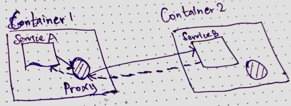
Modern service mesh implementations are proxies which run as sidecar for the services. Generally an agent runs on each node and the services run on the node talk to the proxy and proxy does the service resolution and perform communication.

When Service A wants to talk to Service B

  1. When service A calls its local proxy with the request.
  2. The local proxy perform service resolution and makes the request to Service B
  3. Service B replies to the proxy running in Container 1
  4. Service A receives the response from its local proxy
  5. Service B’s local proxy is NOT used in this communication. Only the caller needs a proxy not the respondent.
  6. Service A is NOT aware of service resolution, resiliency and other network functionalities required to make this call.

There are notable service mesh implementations in the market, Linkered and Istio are quite famous and Conduit is another one and many more in the market. This is a good article explaining those different service mesh technologies.

The mentioned service mesh implementations are known in the Kubernetes and Docker based microservices, but what about service mesh in Service Fabric. 


Service mesh is inherent in Service Fabric

Service Fabric has a proxy based communication system. Defining this as a service mesh is up to the agreed definition of service mesh. Typically there should be a control plane and data plane in a service mesh implementation. Before diving into the details of it, let’s see the available proxy based communication setup in Service Fabric.

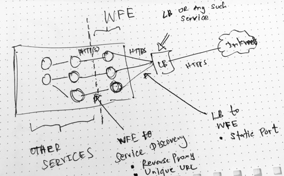
Reverse Proxy for HTTP Communication

SF has a Reverse Proxy implementation for HTTP communications. This proxy runs an agent in each node when enabled. This reverse proxy handles the service discovery and resiliency in HTTP based service to service communication. If you want to read more practical aspect of the Reverse Proxy implementation, this article explains the service communication and SF reverse proxy implementation.

Reverse Proxy by default runs on port 19081 and can be configured in the clusterManifest.json


{

............

"reverseProxyEndpointPort": "19081"

............

}

In the local development machine this is configured in the clusterManifest.xml

<HttpApplicationGatewayEndpoint Port="19081" Protocol="http" />

When Service A wants to call the Service B’s APIs, it calls its local reverse proxy with a following URL structure.

http://localhost:{port}/{application name}/{service name}/{api action path}

There are many variations of reverse proxy URLs should be used depending what kind of a service the calls are made. This is a detailed article about Service Fabric Reverse Proxy.

RPC Communication in Service Fabric

RPC Communications in Service Fabric are facilitated by the Service Fabric Remoting SDK. The SDK has the following ServiceProxy class.

Microsoft.ServiceFabric.Services.Remoting.Client.ServiceProxy

Service Proxy class creates a lightweight local proxy for RPC communication and provided by the factory implementation in the SDK. Since we use the SDK to create the RPC proxy, in contrast to the HTTP reverse proxy this has the application defined lifespan and there’s no agent runs in each node.

Regardless of the implementation both the HTTP and RPC communication are well supported by Service Fabric by native and has the sidecar based proxy model implementation.


Data Plane and Control Plane in Service Fabric

From the web inferred definition of service mesh, it has two key components, (note, now we’re talking the details of service mesh) known as data plane and control plane. I recommend to read this article which explains the data plane and the control plane in service mesh.

The inbuilt sidecar based communication proxies in Service Fabric form the network communication infrastructure : which represents the data plane component of the service mesh. The sidecar proxies in Service Fabric form the data plane. 

Control plane is generally bit confusing to understand, but in short, it is safe to assume  control plane has the policies to manage and orchestrate the data plane of the service mesh.

In Service Fabric, control plane is not available as per the complete definition in the above article. Most of the control plane functions are application model specific and implemented by the developers and some are in built in the communication and federation subsystem of Service Fabric. The key missing piece in the control plane component of Service Fabric is, the unified UI to manage the communication infrastructure (or the data plane).

The communication infrastructure cannot be managed separate to the application infrastructure, thus a complete control plane is not available in Service Fabric.

With those observations, we can conclude:

Service Fabric’s service mesh is a sidecar proxy based network communication infrastructure, which is leaning much on the data plane attributes of a service mesh.

Advertisement

Service Fabric placement constraints and cluster planning : Virtual Clusters

Introduction

This article explains how to achieve a right service placement strategy and Service Fabric (SF) cluster capacity planning. I have written this post as a continuation of this previous article. Continuing the previous article allows me to extend the same contextual problem and find solutions.

According to the previous article, we should place WFE services in certain set of nodes exposed to LB and internal services in a different set of nodes which are not exposed to LB and optionally they may have access to the backdoor database infrastructure.

In fact what I have tried to achieve is a typical infrastructure setup with DMZ and non DMZ. The difference is I have used single SF cluster to hold the DMZ and non DMZ. 

SF is such a powerful and a flexible platform that you can map many kinds of scenarios like this. In SF, we can achieve these logical splits using placement constraints. In its simplest form placement constraints work based on the properties we set to the nodes.

Node properties are key value pairs used to tag nodes. Through the application we then instruct SF to place certain services in certain nodes which satisfy the placement constraint rules.

Placement constraint is the logical composition of node properties which yields a Boolean value to the run time.

NodeProperty1 == "super" && NodeProperty2 == "nvidGPU"

SF will place the node which meets this criteria and place the service in that node. We decorate the node with these node properties and access them in the application and put placement constraints on services.

You can configure the node properties in Azure portal under the node types. If you’re running the on premise setup we can configure it in the ClusterConfig.json. Like any configuration, placement constraints can also be parameterized in the ApplicationManifest.xml using the corresponding parameters xml file. This article describes it very clearly. 

Virtual Clusters

Let’s see how to setup the cluster. In a sample setup with 6 nodes and FD:UD = 6:6, the DMZ and non DMZ setup is made like below. Here DMZ has 2 nodes and non DMZ has 4 nodes.

FD : Fault Domain, UD : Update Domain

cluster setup - virtual clusters

Nodes are marked with NodeType property ex or nex. WFE services have the placement constraint  (NodeType == ex) and internal services have the placement constraint (NodeType == nex).

Node properties make the logical idea of DMZ. Infrastructure and network configuration will give the real separation. In this case we placed ex nodes and nex nodes in different networks and additionally configured a software firewall in between both subnets.

So this placement strategy creates two virtual clusters inside the real cluster. WFE services are placed in the DMZ (red box) and internal services are placed in non DMZ (yellow box).

Dive Deeper

The above virtual cluster setup creates some challenges in cluster planning. Example, though we have FD:UD = 6:6, by imposing the constraint, WFE services have a FD:UD = 2:2 cluster and internal services have a FD:UD = 4:4 cluster.

So overall cluster planning and how SF makes placement decisions are better be understood and simulated for a better understanding. Before diving, I highly recommend to read this article.

So we know, when setting the cluster we have to specify the FDs and UDs, in fact it is the most important step.

In the simplest form FD:UD ratio is a 1:1 setup. It serves majority of the scenarios.

I have played and with this 1:1 mode and I don’t think I will look into other ratios unless there’s a quirky requirement. Also, if you’re using the Azure cluster this is the default setup and I’m not sure whether you can change that. 😉

Though we can have any number of nodes in the cluster, placement of a service is decided by the availability of FD/UDs. Just increasing the number of nodes in the cluster will not result capacity increase.

First let’s look how SF places the services when there’s no placement constraints defined. The default placement approach SF is adaptive approach. It is a mix of two approaches known as Maximum Difference and Quorum Safe. 

  • Maximum difference is a highly safe placement approach where any replica of a single partition will not be placed in same FD/UD.
  • Quorum safe approach is a minimal safety mode, it is chosen when specific conditions are met. Here SF tries to be economical of the node capacity. The replicas belong to a single partition and the quorum will be treated in maximum difference way and others may be placed in same FD/UD.

Instance / Replica : The term instance is used to refer the stateless service copies and replica is used to refer the stateful service copies but in this article I have used the term replica to refer both.

Quorum: A quorum in a stateless service is the number of requested (instance count) replicas, and a quorum in a stateful service is the number of requested minimum replica set size.

If you have read the recommended article, we can summarize the placement approach of SF with a simple pseudo code like below.

rs: replica size, fd : fault domain, ud: update domain n: number of nodes

if ( rs % fd == 0 && rs % ud == 0 && n <= (fd * ud) )
        return "quorum safe"
else
       return "maximum difference"

SF deciding an approach would not yield the successful placement. Because this is just a decision for the placement strategy, once the decision is made SF looks for available nodes which meet the placement criteria.

If there’s not enough nodes to place the services then SF will throw either an error / warning depending on the situation.

FD:UD = 1:1 Case with Virtual Cluster

The below table shows the cluster  simulation. I created this Excel sheet to understand the cluster and added some functions to simulate the cluster. I have translated the high level logical decisions SF makes into simple Excel functions.

Download from : Cluster Visualization Excel

a1

The first section of this report shows the scenario without any placement constraints. So the all FDs/UDs and all nodes are available to all the services.

Replica minimum is a must to have replica count of a partition of a Stateful service. Target replica is the desired number of replicas for the partition. Stateless services have the replica minimum equal to the target number of replicas, because there’s no such idea as minimum replica in Stateless services.

Observations

  1. Row #15 and #16 – Stateless service replica is greater than available FD/UD. Though they are different approaches the bottom line is that cluster does not have enough number of FD/UD. SF reports an ERROR.
  2. Row #9 – Stateful service minimum replica size is greater than available FD/UD. SF will report an ERROR.  This is a very similar case like above.
  3. Row #10 – Stateful service minimum replica size is lower than available FD/UD but target replica size is higher. SF reports a WARNING.
  4. Row #16 – Stateless service replica is greater than available FD/UD. It’s obvious increasing the number of nodes doesn’t make any sense and SF will not use them as long the FD/UD is not expanded. In Row #17 the same scale is achieved with the optimal setup.
  5. Row #22 and #23 – looks same but they have different approaches.  Both run in the warning state because both approaches have met the minimum replica size but not the target replica size.

Second section has the cluster implementation with the placement constraints. So the report is filled with FD:UD 2:2 in ex and FD:UD = 4:4 in nex. Visualizing them as two difference clusters.

Summary

Here I’ve summarized things for quick decision making.

Rule #1:  In stateless services replicas CANNOT scale more than the number of valid fault domains in the cluster. Trying so will cause error.

Rule #2: In stateful services configured minimum (this cannot be lower than 3) replica count of a partition CANNOT scale more than the number of valid fault domains in the cluster. Trying so will cause error.

Rule #3: Whenever possible SF tries to be economical in its placement decision not using all nodes. Consider Row #18 and #19, here in #19 the SF has 4 nodes in four different FD/UD but still decides Quorum Safe.

Like the static node properties there can be dynamic node properties which are also considered in decision making and influences the available FD/UD. In this article I haven’t covered those cases.

In fact if we’re to summarize the ultimatum

If you’re to scale your service (regardless of stateless or stateful) to x number of copies then you should have minimum x number FDs satisfying all specified placement constraints of that service.

It sounds very analogous to a typical stateless web application scale out. 😉

Service Communication and Cluster Setup in Service Fabric

Planning the service communication and the cluster setup is one of the important items we should do when developing on Service Fabric (SF). In this article I have tried my best to stick to the minimalist options in setting up the cluster whilst sufficient details by eliminating the common doubts. The motive behind this research is to find the optimum cluster with little amount of development and ops time.

blog im1

Layering WFE Services

Rule #1 : It is not recommended to open the services to the Internet. You would use a either a Load Balancer (LB) or a Gateway service. In on-prem implementations mostly this would be a LB and your cluster will reside behind a firewall.

The services mapped or connected to the LB act as the Web Front End (WFE) services. In most cases these are stateless services .

Rule #2 : LB needs to find the WFE services so WFE services should have static ports. LB (based on the selection) will have a direct or configured port mapping to these WFE services.

When you create a ASP.NET Core stateless service, Visual Studio (VS) will create the service with following aspects.

  • VS will assign a static port to the service.
  • Service Instance is set to 1 in in both Local.1Node.xml and Local.5Node.xml.
  • Service Instance is -1 in Cloud.xml
  • Kestrel Service listener
  • ServiceFabricIntegrationOption set to None

Since Kestrel does not support port sharing, in the local development environment the Kestrel based stateless services are set to have only one instance whenever a port has been specified.

In you development machine, if you specify an instance which results higher than 1 while a port is specified in the ServiceManifest.xml for service which Kestrel listener, then you will get the following famous SF error.

Error event: SourceId='System.FM', Property='State'.
Partition is below target replica or instance count

The above error is about, Failover Manager (FM) complaining that SF cannot create replicas as requested. In FM’s point of view, there’s a request to create more instances but due to port  sharing issue in Kestrel, SF cannot create more than one instance. This is the same error you would get regardless 1 node / 5 node setup because because physically we use one machine in development.

Using HttpSys listener is an option to overcome this issue. In order to use the HttpSys listener install the following NuGet package, update the listener to HttpSysCommunicationListener and the ServiceManifest.xml as below.

Install-Package Microsoft.ServiceFabric.AspNetCore.HttpSys


protected override IEnumerable<ServiceInstanceListener> CreateServiceInstanceListeners()
{
return new ServiceInstanceListener[]
{
new ServiceInstanceListener(serviceContext =>
new HttpSysCommunicationListener(serviceContext, "GatewayHttpSysServiceEnpoint", (url, listener) =>
{
ServiceEventSource.Current.ServiceMessage(serviceContext, $"Starting HttpSys on {url}");
return new WebHostBuilder()
.UseHttpSys()
.ConfigureServices(
services => services
.AddSingleton<StatelessServiceContext>(serviceContext))
.UseContentRoot(Directory.GetCurrentDirectory())
.UseStartup<Startup>()
.UseServiceFabricIntegration(listener, ServiceFabricIntegrationOptions.None)
.UseUrls(url)
.Build();
}))
};


<Endpoints>
<Endpoint Protocol="http" Name="GatewayHttpSysServiceEnpoint" Type="Input" Port="8080"/>
</Endpoints>

In fact, in the production deployments when more than one node available we can use Kestrel listener with static port mentioned in the ServiceManifest.xml with more than one instance.  SF will place the instances in different nodes. This is why the instance count is set to -1 in Cloud.xml.

Here the -1 is safe, because setting a specific number for instance count while Kestrel is used in static port mode may create issues when the requested instance count exceeds the nodes available for SF to place the service.

Common Question: Can we use HttpSys listener and enable scaling ? This is possible but most cases specially in stateless services scaling number of instances is the typical scale out scenario. So there’s no point having a scale out strategy in a single node by congesting a node with many number of services, because running multiple instances in same the same node will not yield the desired throughput we need. Also in such cases Cluster Manager will not find enough nodes with UD/FD combination in order to place the instances and provide a warning message.

Do not make the mistake that I favor Kestrel over HttpSys in this article, there are specific cases where you need HttpSys over Kestrel. In Microsoft articles Kestrel being mentioned and most of the cases are given in such a way that Kestrel can be used to reach desired output regardless of its inability of handing port sharing. From ASP.NET Core point of view Kestrel is good as long as your service is not directly facing the Internet.

Best Practice : Do NOT place WFE services in all nodes. Have dedicated nodes for the WFE services (use placement strategies). This allows stronger separation between WFE nodes and internal nodes. We can also implement a firewall between WFE service nodes and internal service nodes. In another way we trying to achieve the WFE and application server separation we used to do in N-Tier deployments. (to be honest I winked a little bit here when thinking of microservices)

Layering Internal Services

WFE services will route the requests to the internal services with the specific service resolution. Communication from WFE services to the internal services are generally based on HTTP because this provides loose coupling between the WFE services and internal services.

First let’s see what should happen when WFE wants to route a request to the internal services.

  1. WFE should resolve the service location – either via Naming Service directly or via the SF Reverse Proxy
  2. Services should have unique URLs (apart from the IP and port) because when services move from node to node, one service can pick the same port from a node which was used by the previous service and could cause issues. – In such cases a connection can be made to a wrong service (read more from this link)

Rule #3: It is recommended to use SF Reverse Proxy for internal HTTP service communications, because it provides features like endpoint resolution, connection retry, failure resolution and etc.

Reverse Proxy should be enabled in the cluster with the HttpApplicationGatewayEndpoint tag in ClusterManifest.xml. The default port for reverse proxy is 19801 and this service run in all the nodes. You can customize this via ClusterManifest.xml

WFE services should resolve the internal services (first layer services which has HTTP communication from WFE services) using SF Reverse Proxy.

http://localhost:19801/ApplicationName/InternalServiceName/RestOfTheUri

The localhost is applicable as the request is sent via the Reverse Proxy agent running on the node which is calling the internal service. The above URL will be used in a simple HTTPClient implementation to make the call. The below snippet shows a simple GET request.


string reverseProxyUrl = "http://localhost:19801/ApplicationName/InternalServiceName/RestOfTheUri";
var httpClient = new HttpClient();
var response = await httpClient.GetAsync(reverseProxyUrl);

Things to be noted in SF Reverse Proxy

The above URL is the simplest form for a reverse proxy URL which resolves a stateless services. Since This article assumes the 1st layer internal services are stateless the above URL structure will work – no need to mentioned the partition id and kind. In order to learn the full URI structure read this link

Reverse Proxy does retries when a service is failed or not found. Not found can happen when a service is moved from the requested node. Not Found can also occur when your internal service APIs return 404 for a not found business entity. Reverse Proxy requires a way to distinguish between these two cases because if it’s a business logic which returns 404 then there’s no point retrying. This scenario is explained in above article.  In order to avoid a wrong service being called internal stateless services should be have unique service URL integration.

In order to mitigate this, internal services should tell the Reverse Proxy not to retry with the header value. You can do this with an IResultFilter implementation like below and apply the attribute to your controllers. So any action method returns 404 (business service aware 404) values will have this header and Reverse Proxy will understand the situation.


public class ReverseProxyServiceResponseFilter : IResultFilter
{
public void OnResultExecuted(ResultExecutedContext context)
{
if(context.HttpContext.Response.StatusCode == 404)
{
context.HttpContext.Response.Headers.Add("X-ServiceFabric", "ResourceNotFound");
}
}
public void OnResultExecuting(ResultExecutingContext context)
{
}
}

So in this mode the internal stateless services which uses HTTP endpoints should have following aspects

  • Dynamic port assignment
  • Kestrel Service listener
  • Can scale the service instance as long as FD:UD constraints are not violated
  • No restrictions in dev enviornment
  • ServiceFabricIntegrationOption set to UseUniqueServiceUrl

Note: User revers proxy for internal HTTP communication. Clients outside the cluster SHOULD connect to the WFEs via LB or any such similar service. Mapping Reverse Proxy to the LB can cause the clients outside the cluster to reach the HTTP service endpoints which are not supposed to be discoverable outside the cluster.

Summary

Let me summarize the items in points below.

  • Use Kestrel for WFE with static port assignment with placement strategies for the nodes allocated to handle WFE workload.
  • Using HttpSys for WFE is fine, but do not use this in the intention of scaling out thus would not yield the right expected result.
  • Use Kestrel for internal HTTP stateless services with dynamic port allocation and enabling unique service URL.
  • Use SF Reverse Proxy for internal HTTP communications whenever possible
  • It is not recommended to map the SF Reverse Proxy the external LB or Gateway service.


In the endpoint configuration services have endpoint type which can be set to Input or Internal. I did some testing but failed as both types exposes the services as long as they have a valid port mapping to LB. Finally ended up asking from the creators and this is the answer I got. So technically endpoint type does not matter.