Shadow IT – Tradeoff between frictionless user experience and being responsible with AAD V2

Introduction

First let me begin with ‘What is meant by Shadow IT ?’. In a broader view shadow IT is, any sort of IT usage without the direct governance of IT department of your organization.

Sometimes this remains as a violation of the company policies, but the proliferation of the cloud SaaS applications and BYOD trends makes shadow IT an unavoidable practice.

100-cloudtweaks-comic

A simple example would be a cloud based file sharing application used in an organization which is not officially approved by the IT.

In most cases organizations are not aware of the tools used by their employees and shadow IT usage. Only 8% of the organizations are aware of their shadow IT usage.

percentage shaow it

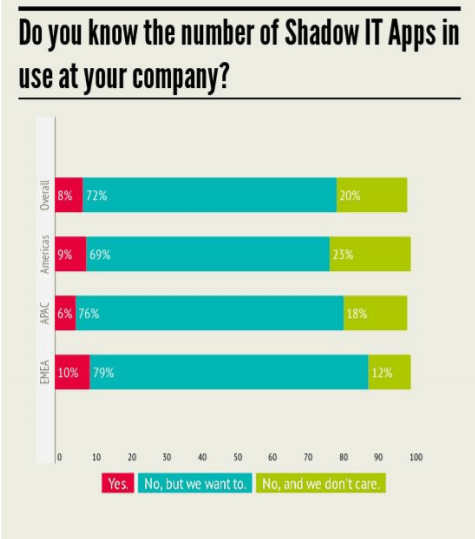
Taken from – Cloud Adoption Practices & Priorities report 2015 : Cloud Security Alliance.

In my opinion there are two major reasons which fuel the increasing shadow IT practices. First, when employees have higher and diversified devices than the ones available at work. Secondly when they find sophisticated SaaS tools than the ones available at work.

Another notable reason is – communication between contextual boundaries, like departments, SBUs and other companies – people tend to use cloud based SaaS tools either for convenience or due to some already existing shadow IT practices of a party.

How to with AAD V2

So, what is the importance in software development in shadow IT ? –  One of the projects I’m involved with has been going through the transformation of being an internal system to a public system. We decided to open this up as a SaaS tool that anyone with a Azure Active Directory (AAD) credential can use it.

Behind the scenes the application has rules to track the user, tenant, recurrence of the tenant, other users in the tenant and the list grows. But anyone with a valid AAD account can simply create an account and start using it. This makes the application a perfectly fitted candidate in Shadow IT. It’s a perfect Shadow IT tool.

As SaaS provider we want many users as possible using our system, after all we charge per transaction 🙂

  • The application is registered as a AAD V2 app in the home directory.
  • We removed the friction in the enrollment by keeping only the minimal delegated permission (User.Read) in the app.

But in order to provide more sophisticated experience inside the application we require access to AAD and read permissions on other users. In order obtain this we thought of an approved shadow IT practice via application permissions.

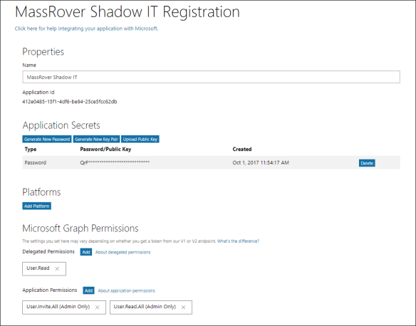
  • We added the admin privileges to the application permissions, and generated application secrets.

The configured AAD V2 app principle look similar to the below one.

b1.PNG

In the experience point of view, we trigger the typical following normal AAD login URL for the user login. We trigger the organization endpoint (restrict the Microsoft accounts) with the following URL. (You can try the URL)

https://login.microsoftonline.com/organizations/oauth2/v2.0/authorize?client_id=412e0485-15f1-4df6-be94-25ce5fcc62db&response_type=id_token&redirect_uri=https://localhost:8080&scope=user.read openid profile&nonce=3c9d2ab9-2d3b-4

This will popup the login and after the successful validation of the credentials you’ll see the following consent screen.

b3

User accepts the consent and she’s inside the SaaS application Shadow IT begins here. In order to get the additional rights we allow the user to inform her IT administrator and ask for additional permission.

IT administrator will be notified by the email entered by the user with following admin consent link.

http s://login.microsoftonline.com/[tenantid]/adminconsent?client_id=412e0485-15f1-4df6-be94-25ce5fcc62db&response_type=id_toke&redirect_uri=https://localhost:8080

Here we obtain the tenant id from the id_token from the user logged in previous step. When the IT administrator who has admin rights in the AAD hits the above URL and after successful validation of the credentials he will see the following admin consent screen.

b4.png

The permission list varies based on the configured application permissions in the application. After successful consent grant, the redirection will happen to a URL similar like this

http s://localhost:8080/?admin_consent=True&tenant=[tenant id]

Now the application can use the app secret to access the specific tenant.

NoteFrom AAD principle point of view, the service principle of the application is registered in the tenant in the first step. (This configuration should be allowed in AAD – by default this is enabled) and during the admin consent process the service principle gets more permissions granted to it. 

Summary

We achieved both the frictionless experience for the user and allowing administrator to grant the permission when required. The below image summarizes the process.

b5

  • By request IT admin knows the usage of application and it give some light to the usage of such SaaS.
  • By granting access IT admin allows it to the organizational use and removing shadow IT context.
  • If admin rejects the consent the organizational user knows that he’s in Shadow IT context.
  • Blocking of such SaaS may continue based on the organizational policies.


Advertisement

Multi tenancy – A myth in the cloud

Multi tenancy is a popular buzzword, often heard coupled along with cloud computing terminology. This is the issue and has created a dogma and some believe that multi tenancy can only be related with the cloud and cloud based SaaS services.

Based on the definition from Wikipedia

The term “software multitenancy” refers to a software architecture in which a single instance of software runs on a server and serves multiple tenants. A tenant is a group of users who share a common access with specific privileges to the software instance….

The core concern is – Pragmatically it is hard to define what a single software instance is ?

If multi tenancy is all about handling group of users (as tenants) we’ve been doing that with our good old, role based software systems, that’s not something new.

If we consider about the single instance of a software system, then there are confusions on how to consider the scale out scenarios and replications. (do not forget the DR plans with read access). In the software instances there could be confusions in the granular levels of programmatic constructs as well, like – are we talking about application level mutexes or object level singletons.

Handling different group of users in a software is very common scenario.  We see this problem in different layers of a software solution – in terms of data partitioning, security, noisy neighbor issues and much more.

But taking a SaaS solution and pointing the whole as a multi-tenant or non multi-tenant solution is technically wrong, though it has some conceptual truth in it.

In particular it becomes really annoying when someone tells that cloud supports multi tenancy and moving to cloud will give the ability to support multiple tenants.

Let’s see how things get complicated, consider a simple scenario where organizations (for the ease of understanding the tenants) can upload and convert videos to desired formats and stream them online.  Look at the below diagram in a simple overview. (note – the connections and directions do not reflect any and only data flow)

18-01-2017-20-53-office-lens

Here, the WFE is a web application and runs in single web server (multi tenant ?), and the service layer is running on two machines with the load balancer. (multi tenant ? or not) Web application access the cache which is a single instance serving as a common cache for all tenants. (multi tenant ?)  Messaging Queue, storage and transcoding services also runs single instances (multi-tenant ?) Each tenant has a different dedicated database (single tenant ?).

So in the entire system each layer or the software infrastructure has its own number of instances – so it’s almost impossible to call an entire system as multi tenant in technical perspective.

As a business unit, the system supports group of users (organizations in the above example) and regardless of the cloud or not, it is a multi tenant system.

Hope this will clear the misunderstanding of believing or arguing a SaaS is a multi tenant or just because moving a solution to cloud would make it multi tenant.

Managing multiple sites with Azure Traffic Manager and deployments using TFBuilds

Introduction

Azure Traffic Manager is used to mange the traffic of your Internet resources and monitor the health of those resources. These resources may reside outside the Azure as well.

This post is focused on Azure Web Apps and how to manage multiple web apps using Azure Traffic Manager and handling deployments using new TFBuild of VSTS.

Consider a scenario of having two deployments of your site in different regions, one in the South East Asia and the other one in the North Europe. The site is deployed in two places in order to cater the users from each region with minimum latency. Traffic Manager is deployed in place in order determine the resource usage and directs the clients to the right location.

First when a client requests the site, the request hits the DNS, the DNS records have the mapping of the URL to the Traffic Manager DNS and it makes a lookup request to the corresponding Traffic Manager DNS.

Then the Traffic Manager DNS will deliver the right IP address of the web app based on the configured routing rules. This IP address will be given to the client, subsequent requests from the client will be sent directly to the obtained IP address until the local DNS cache expires.

Setting up Traffic Manager

Create a Traffic Manager space and you will get a URL like domainprefix.trafficmanager.net(The below sample I generated when while sipping my iced tea and named the Traffic Manager mytea). When creating the Traffic Manager you will configure the load balancing mechanism. Here I simply chose Performance as my load balancing mechanism since I want to reduce the latency of the site based on the geographic region it is accessed from.

image

Then you add the web apps you want to manage to the Traffic Manager as endpoints. (Note, only web apps running in the standard or upper tier are allowed to be added to the Traffic Manager)

I added two web apps one in South East Asia and the other one in the North Europe as you can see in the below image.

image

How does this work ?

After creating the Traffic Manager profile (mytea.trafficmanager.net), you will add the endpoints. When adding the endpoints, the Traffic Manager will register its URL as one of the domain names in mentioned web apps. The web app URLs are registered as CNAME entries of the Traffic Manager DNS.

image

How does this work when you have a custom domain ?

When you have a custom domain, example abc.com you register that domain in the above section, and you configure the azure web app URL as a CNAME record in the abc.com domain. Now when you type abc.com in the browser you will be served with the site.

In a more simpler way, the DNS entry which holds the A record of abc.com should have CNAME record to point to the Azure web app.

When using the Traffic Manager, you register the traffic manager URL as a CNAME entry in the abc.com.

Managing deployments to multiple web apps

This had been one of the well known and highly anticipated requirement of CI/CD pipeline. But with the new TFBuilds introduced in Visual Studio Team Services it is very simple. You can simply add multiple deployments steps in your build definition and the TFBuild will take care of your deployment.

Below image shows a build definition with two azure web app deployment endpoints.

image

Testing

Now you can type the Traffic Manager URL in the browser with the http/https prefix and you will be served with the site.

In order to check the performance routing of the region I changed the home page of the site deployed in North Europe. Then I browsed the site using a VM deployed in North Europe and browsed it from local machine where my physical location is closer to the South East Asia.

image

image

You can see that two different sites are served based on the location from where I’m browsing the site.

Circuit Breaker Pattern for Cloud based Micro Service Architecture

Modern applications communicate with many external services; these external services could be from third party providers or from the same provider or they are components of the same application. Micro service architecture is a great example for disconnected, individually managed and scalable software components that work together. The communication takes place using simple HTTP endpoints.

Example: Think that you’re developing a modern shopping cart. Product catalog could be one micro service, ordering component would be another one and the user comment and feedback system would be another one. All three services together provide the full shopping cart experience.

Each service is built to be consumed by each other, they might have sophisticated API Management interfaces or just a simple self-documented REST endpoints or undocumented REST endpoints.

Another example is Facebook, it has messenger feature implemented by a totally different team from who manage the feeds page and the Edge Ranking stuff. Each team push updates and individually manage and operate. The entire Facebook experience comes from the whole collection of micro services.

So the communication among these components is essential. Circuit Breaker (CB) manages the communication by acting as a proxy. If a service is down, then no point trying it and wasting the time. If a service is being recovered, then better not to congest it with flooded requests; time to heal should be given to the service.

Circuit Breaker and Retry Logics

It is important to understand when to use Circuit Breaker and when to retry. In case of transient failures, application should retry. Transient failures are temporary failures; a common example would be TimeOutException. It is obvious that we can retry for one more time.

But think an API Management gateway blocks your call for some reason (IP restriction, Request Limit) or any 500 error then you should stop the retry and inform the caller about the issue. And let the service heal. This is where Circuit Breaker helps.

How Circuit Breaker Works?

Circuit Breaker has 3 states.

  • Closed
  • Open
  • Partially Open

Look at the below diagram and follow the context for the explanation.


By default, Circuit Breaker is in the Closed state. The first request comes in and it will be routed to the externa service. Circuit Breaker keeps a counter for the non-transient failures occur in the external service in a given time period. Say that the given time period is 15 seconds and the failure threshold is 10, if the service fails 10 times within 15 seconds for n number of requests then Circuit Breaker goes to Open state. If there’re no or less than 10 failures during 15 seconds, the failure counter will be reset and Circuit Breaker remains in Closed state.

In the Open state, Circuit Breaker does not forward any requests to the external service, regardless of how many requests it receives. It replies to those requests with the last known exception. It remains in the Open state for a specified time period. After the Open state has elapsed Circuit Breaker enters the Partial Open state / Semi Open State.

In the Partial Open state, some of the requests are being forwarded to the external service while others are being rejected as Circuit Breaker is in Open State. In the allowed number of requests Circuit Breaker monitors the success of those calls, and if a specified number of calls are continuously successful then Circuit Breaker resets it counters and goes to the Closed state.

The mechanism of which calls should reach the service during the Partial Open state is up to the implementation. You can simply write an algorithm to reject one call after the other or you can use your own business domain. Example calls from members of Admin role can pass through and others fail.

Partial Open State and preventing Senseless blocking.

This is a bit tricky state because, this state does not have a timeout period. So Circuit Breaker will remain in the Partial Open state until the right number of requests come to satisfy the condition. This might not be preferable in some cases.

Example, consider the service is down at 10:00:00AM and Circuit Breaker goes to Open state. After 3 minutes (at 10:03:00AM) it goes to Partial Open state. From 10:03:00AM to 10:23:00AM only few requests came and some of them will be rejected by the Circuit Breaker, and still Circuit Breaker is waiting for more calls though the service is perfectly back to normal by 10:08:00AM. I named this kind of prevention from the Circuit Breaker as Senseless Blocking.

There are few remedies you can implement to prevent senseless blocking. Simply we can put a timeout period for the Partial Open state or we can do a heartbeat check from the circuit breaker to the external service using a background thread. But be mindful that senseless blocking is an issue in Circuit Breaker pattern.

When not to use Circuit Breaker?

When you do not make frequent calls to the external service, it is better to do it without going through a Circuit Breaker, because when your calls are not frequent there’s a high probability that you might face senseless blocking.

Implementation

I have provided a reusable pattern template for the Circuit Breaker.

Code is available in GitHub : https://github.com/thuru/CloudPatterns/tree/master/CloudPatterns/CircuitBreakerPattern


Cached-Aside Pattern using Redis on Azure

Cache-Aside is a common pattern in modern cloud applications. This is a very simple and a straight forward one. The followings are the characteristics of the pattern.

  • When an application needs data, first it looks in the cache.
  • If the data available in the cache, then application will use the data from the cache, otherwise data is retrieved from the data store and the cache entry will be updated.
  • When the application writes the data, first it writes to the data store and invalidates the cache.

How to handle the lookups and other properties and events of the cache are independent, meaning the patters does not enforce any rules on that. These diagrams summarize the idea.

  1. Application checks the cache for the data, if the data in the cache it gets it from the cache.
  2. If the data is not available in the cache application looks for the data in the data store.
  3. Then the application updates the cache with the retrieved data.

  1. Application writes the data to the data store.
  2. Sends the invalidate request to the cache.

Implementation

Project : https://github.com/thuru/CloudPatterns/tree/master/CloudPatterns/CacheAsidePatternWebTemplate

The above project has an implementation of this pattern.

Data objects implement an interface ICacheable and an abstract class CacheProvider<ICacheable> has the abstract implementation of the cache provider. You can implement any cache provider by extending CacheProvider<ICacheable>. GitHub sample contains code for the Azure Redis and AWS Elastic Cache implementations.

Implementation of ICacheable : https://github.com/thuru/CloudPatterns/blob/master/CloudPatterns/CacheAsidePatternWebTemplate/Cache/ICacheable.cs

Implementation of CacheProvider<ICacheable>: https://github.com/thuru/CloudPatterns/blob/master/CloudPatterns/CacheAsidePatternWebTemplate/Cache/CacheProvider.cs

Implementation of AzureRedisCacheProvider : https://github.com/thuru/CloudPatterns/blob/master/CloudPatterns/CacheAsidePatternWebTemplate/Cache/AzureRedisCacheProvider.cs

The template also includes Cache Priming in Global.asax. This could be used to prime your cache (loading the mostly accessed data in the application start)