Deep Dive into Azure Managed Identities – Behind the scenes

Introduction

Sometime back when it was in the preview, I posted an article on Azure Managed Service Identity (MSI) and how we can use it, to eliminate storing credentials in the code, whilst avoiding the bootstrap problem. Read the link for more details.

This post is about Managed Identity, in short, Managed Identity is the new name for Managed Service Identity. Though the purpose and the functionality stay the same, Managed Identities provide more granular control, Azure Portal options and sophisticated improved SDK support, which convinced me enough to write a post.

Managed Identities is a feature of Azure Active Directory (free to use), which helps to eliminate storing credentials in the code. Since, Managed Identities is a feature of AAD, it can be used to authenticate to any Azure service that supports AAD authentication. Let’s start from AAD and drill down into the Managed Identities.

AAD Principles

AAD can have two different principles, user principle and service principle. A user principle is a user object, and a service principle is an instance of application registration.

1

So what is an application in AAD ?  An application is a global template for a service principle. The directory (AAD tenant), the application is registered is known as the home directory. When the permissions / consent has been given to a application the service principle object is created.

Other than the creation and configuration phases, what we deal with is a service principle. I recommend you to use the terms user principle, service principle and application to have the clear understanding in the communication. You can read more about the application and service principle from this link

Managed Identities

Managed Identities are special type of service principles, they are two types.

User assigned Managed Identity – Available to create as a standalone Azure resource. Should be created manually, when created, a corresponding AAD application will be registered (more details below). One Azure resource can have many user assigned managed identities. The life cycle of a user assigned managed identity is independent of the resource life cycle, meaning a user assigned managed identity can exist without being attached to any resource.

System assigned Managed Identity – These are created by Azure when enabling the Managed Identity for a service. The lifetime is scoped to the lifetime of the resource. One service can have only one system assigned Managed Identity.

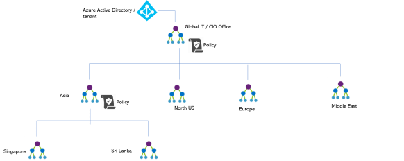
The below image summarizes the things. Mindful this, is a specific diagram I have created to illustrate the AAD principles. AAD is not limited to below context.

aad managed identities full.PNG

Enabling Managed Identities to a Service (App Service)

I take a simple example of how we can use Managed Identities to access a Azure Key Vault, which contains the secrets.  This article covers creation and assignment of the Managed Identities to App Service, —

app service capture

System Assigned Identity, we have to enable and in the second tab, you can see the User Assigned identity (still in preview).

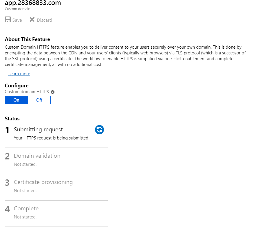
Enabling System Assigned Managed Identity 

Switch the status to ON and this will create a system assigned managed identity. Just to explain what is happening behind the scenes.

Before enabling run this PowerShell command (you need GA permissions to the tenant) to see the number of service principles in the AAD.


(Get-AzureRmADServicePrincipal).Count

view raw

gistfile1.ps

hosted with ❤ by GitHub

This will give you the number of service principles in the AAD, and after enabling the System Assigned Managed Identity when you run the above command the count will be +1. Also in the portal, you can see the object id of the service principle.

2

Executing the below will give the details


Get-AzureRmADServicePrincipal -ObjectId db9c6f9e-bea0-4325-b18c-dcd6eda668af
ServicePrincipalNames : {98b1ebaf-b6b2-4368-ba53-c36ae0551b90, https://identity.azure.net/4zuSVB9vvyfEk5wvTupj9aFQnGVY0bvqMPfQ9bTKrwk=}
ApplicationId : 98b1ebaf-b6b2-4368-ba53-c36ae0551b90
DisplayName : chimp01
Id : db9c6f9e-bea0-4325-b18c-dcd6eda668af
Type : ServicePrincipal

Behind the scenes, Azure has created a service principle for us. In the portal, under Enterprise Applications, make a search with the Display Name (retrieved from PowerShell), you will see the associated service principle. (make sure, you have selected All Applications in the drop down)

But, this is a special kind of a service principle, which we cannot configure any explicit permissions. If you navigate to the Permissions section you will notice that.

Enabling User Assigned Managed Identity

This is still in preview, and in the second tab of the Identity blade. Here we add a Managed Identity as a standalone resource in Azure. You can add an existing user assigned Managed Identity in the tab as shown below.

Screen Link 001

3.PNG

In order to create a User Assigned Managed Identity,  you can add it in the portal, as a separate resource. Search for User Assigned Managed Identity, and click create.

4

This is like any other Azure resource creation, fill the details and create it.

5.png

After creating the User Assigned Managed Identity, run the above count script, you will see one more service principle in AAD tenant.

Also, if you search the resource name under the Enterprise Applications (All Applications enabled) you will see the service principle.

Additionally, we can see the created Managed Identity as a resource in the specified Resource Group.

6

Now go back to the screen link 001, and you can add the created user assigned Managed Identity.

7

As you can see, we can add more than one user assigned managed identities to a Azure service.

Continuation

We have created and assigned the Managed Identities to our service, next article will explain how to use them both in production and development.


Democratizing Enterprise Cloud in Azure

Cloud is the new normal; almost, all the enterprises have been going through or at least planning their cloud adoption. Gone are the days, enterprise IT deals with big chunks of metal.

Though the cloud adoption is at its peak, I rarely see democratized cloud adoption in enterprises. Cloud is often used as a centralized IT hosting solution. In this article, let’s analyze the issues for such cases, and what are the options available in Azure to enable democratized cloud adoption with enterprise governance.

It is predicted that, 83% of the workloads will be running in some form of cloud in 2020, where 41% on public cloud.

where IT workloads will run in 2020 : aventude

https://www.logicmonitor.com/wp-content/uploads/2017/12/LogicMonitor-Cloud-2020-The-Future-of-the-Cloud.pdf

Cloud is not only the successor of IT assets and management, but also, it has evolved to provide agility and innovation at scale. These aspects, have been changing the way organizations deal with technology along with other techno-cultural and techno-commercial shifts like DevOps, PaaS and Opex.

public cloud drivers aventude

https://www.logicmonitor.com/wp-content/uploads/2017/12/LogicMonitor-Cloud-2020-The-Future-of-the-Cloud.pdf

As per the above graph, the key motives are agility, DevOps and innovative aspects.

In order to leverage the full potential of the cloud, it is mandatory for the enterprise IT to deliver cloud with its real essence. This will help the cloud adoption, without putting the key motives under threat.

If your enterprise has cloud but still require calls, emails and requests to spin up a resources or to make change, it kills the agility the cloud naturally offers. It’s like buying a Ferrari and restricting it to go in 20 kmph.

Once the agility is killed, innovation is blocked, and soon the cloud becomes a mere hosting solution.

A successful enterprise cloud adoption is not just things are in the cloud, it should be democratized with proper governance, in order to leverage the agility whilst maintaining the governance.

What makes the enterprises not to democratize their cloud adoption?

In most enterprises, the cloud adoption is strictly controlled by the IT, often tampering the autonomy of the business agility and digital transformation cadence.  There are several reasons for this.

  • Cloud Sprawl – Organizations fear cloud sprawl, cloud sprawl refers to the unwanted/uncontrolled cloud footprint, which leads to unnecessary cost.
  • Security – Concerns about security implementations, how the resources should be created, linked, managed and monitored. This knowledge mostly stays with the IT teams and often sensitive, this leads the IT to keep the management within themselves.
  • Governance and Policies – Organizational policies in terms of access levels and governance should be adhered, this is an organizational knowledge (internal) where it often remains tacit. Example – Organizational policies in firewall settings? Patch administration and etc.
  • Unified Tools and licenses – Larger enterprises, especially who have complex IT structure should leverage the maximum return of investments they have made on tools and licenses. So certain tools and licenses are commonly used and certain things are prohibited (partner relationships also play a significant role here). Historically, IT has the knowledge and the relationship management of these tools and license offerings, it creates a dependency on IT to decide on tools and licenses. Example – What license to bring to cloud? what are the available ones? Do we have any alternative tools in-house and etc.
  • Lack of cloud knowledge – Lack of knowledge about the cloud and offerings. Business stakeholders often get confused and try to compare things in wrong ways, this kind of experience often leads the IT to keep the cloud as a black box as possible and forces the IT to centrally manage the cloud.
  • Centralized culture – Enterprises have cultural problems that often create authoritative and knowledge pools, which blocks the democratization of the technology and decision making.

With all these challenges, Finding the right balance between autonomy and the governance is the key.

What Azure has in place?

Earlier, Azure subscriptions are part of a tenant, and under the subscription we have resource groups and then the resources. This hierarchy is very basic and it does not have the flexibility to govern and mange enterprise complexity.

Azure got a new hierarchical elements in structuring enterprise cloud footprint closer to the organizational structure.

The below figure shows the current new structure.

azure management group hierarchty

These management groups can have policies to ensure the governance. Policies can be set at any level. Policies by default inherit the permissions from the level above.

Policies can be very granular like which restrict resource types, SKUs and locations, policies to ensure security aspects like patch, endpoint controls and etc.

Use Cases and structuring

There’s no hard and fast rule on how do we structure the management groups and subscriptions, but it is often better to follow the organizational decision tree. Below are some common structuring approaches.

One organization with departmental separation

aventude: departmental management group structure

Global organization with geographic footprint

aventude : global management group structure

Conglomerates

aventude : conglomerate management group structure :


Once the right policies are in place, IT can take a relax approach, like a development team shouldn’t create that big VM, you are always afraid of.

Though, the above hierarchical approach gives lots of flexibility, in certain cases still you may find challenges to address the hierarchical management, especially in the group of companies, where each company has its own CIO office and some policies are controlled centrally. Also, when these business units use different tenants it adds more complexity to the picture.

Regardless, of the tools – the key point I want to stress out from this article is – in enterprise cloud adoption IT teams and management should focus on democratizing the IT much as possible whilst maintaining the governance policies intact.  Too much control at central place will tamper the agility of the cloud and kills the momentum of the digital transformation.


Optimizing Web delivery of the modern front end Applications

JavaScript based front end frameworks have made their unprecedented dominance in application development, even beyond the web. Single Page Application (SPA) delivery is one big aspect of the modern software development.  

Though the engineering aspect has changed over time with many frameworks and tools, the underlying fact of, they are static files haven’t changed. This gives the opinion of serving those static content, from the locations closer to the consumer, rather than from a remote web server.

This will give high performance by reducing network latency. In this article let’s see how to deliver a SPA or any static content with Azure DevOps with the best optimum setup in terms of performance and cost.

Approach

Follow the below approach……

  • Enabling and hosting the static website in Blob Storage
  • Setting up Azure DevOps pipeline
  • Setting Custom Domain
  • Optimization with edge using CDN and enable SSL
  • Azure DevOps considerations in CDN delivery

Enabling & hosting static website in Blob

You can create a standard blob storage in Azure. You will get the static website feature by default, you should enable it for the use. 

Static website hosting has a special container named $web, which is the www root of the static website.

Normally, Blob storage does not allow us to create containers with non alphanumeric characters, but this is a special container created for static website hosting. 

You will get two endpoints primary and secondary. Both will point to the index document. You can upload the index document. You can optionally configure the error document as well.

In this case index.html is used for both.  For testing purposes, just upload a simple html file with the name index.html, then browse any of those endpoints, then you would see the uploaded index.html.

This confirms the Blob storage static web hosting has been enabled and working properly. 

Setting Azure DevOps Pipeline

Now, we have to setup the DevOps pipeline for Continuous Integration and
Continuous Deployment.  Regardless of the framework you use for development (React, Angular, Vue, WebAssembly or anything that came today morning) – end of the day the build artifacts should be bundled as static files.

Different frameworks require different build steps and it varies based on the project context as well. Once the build is completed the artifacts should be uploaded $web container of the Blob storage.

In Azure DevOps you can use Azure Blob File Copy build step to achieve this. This will copy the pointed artifacts to the specified container.

Note, use the version 2* (still in preview as of this writing) the previous versions would complain that a container name cannot be validated with $ character

Custom Domain in Azure Blob static website hosting

Let’s setup a custom domain to our static web site, this would be one important step you require to accomplish in production.

You can use your DNS management or migrate your domain to Azure DNS Zone.

I have used Azure DNS Zone – Go to your DNS settings and create a CNAME record with one of the endpoints as below.

You cannot create a DNS ‘A’ record here, because Storage doesn’t provide a IP.

Because we do not have an ‘A’ record mapping in the DNS, the downside of this is, that we can browse http://www.28368833.com but we CANNOT resolve http://28368833.com

Optimization with edge using CDN and enable SSL

You can further optimize the delivery by bringing the content files to the CDN. Configure a CDN endpoint to the Azure Blob storage.

Delivering via CDN allows to have SSL enabled as well.

Create a CDN endpoint in a CDN profile.

Select the Custom Origin and enter the static website host name of the Blob storage. DO NOT select the Storage as origin type.

Now if you browse through the CDN endpoint (https://aventude-spa.azureedge.net) you will see the web page (the change need sometime)

Since we have changed the delivery address to the CDN, now we have to map the domain to the CDN endpoint. This is quite straightforward as the previous step. You have to create a CNAME entry pointing the CDN endpoint.

Once done, you can navigate to the custom domains in the CDN endpoint and enable the custom domain HTTPS.

Azure DevOps Considerations in delivering in CDN Delivery

When the delivery is optimized via CDN – Whenever we do the artifact publishing to the Blob storage – either we have to purge the CDN or wait for the content to propagate.

Most of the cases, purging is the recommended approach. Azure DevOps has a handy Purge Azure CDN endpoint build step.

This step will trigger the purge operation and changes will be immediately available once purge is completed.

Azure CDN provides DSA (Dynamic Site Acceleration) delivery, in this case purge is not required. Because the content is not stored in the CDN.

In the DSA mode, what CDN does is, optimize the route path from the caller to the origin in the best possible way. If your static content has frequent changes then this approach is recommended over purging.

DSA should be enabled at the time of CDN endpoint creation.

Following drawing summarizes the whole idea here.

You can choose the delivery at the Blob storage level or at the CDN level. The mechanism from the Blob storage to CDN changes based on the update frequency of the content.

Also, note – as stated earlier both the Blob storage and CDN does not allow us to have A record mapping in the DNS. This may be a drawback, but in most practical cases, the front end applications are delivered with the sub domain URL like app.<domain>.com.

In case you need to resolve A record like https://28368833.com, you should do a URL rewrite from the mapped A record destination IP.

Service mesh in Service Fabric

Introduction

Microservices is here to stay and we can witness the increasing popularity and the maturing technology stack which facilitate microservices. In this great article which explains about the maturity of microservices and the 2.0 stack, it mentions three key aspects.

  1. Service mesh
  2. Matured orchestrators
  3. RPC based service protocols.

This post focuses on the communication infrastructure in Service Fabric. Service Mesh is about the communication infrastructure in a microservices / distributed system platform.

First, let’s look at What is a service mesh ?  In the simplest explanation, service mesh is all about service to service communication. Say, service A wants to talk to service B, then Service A should have all the network and communication functionality and the corresponding implementations, in addition to its business logic. Implementation of the the network functionality makes the service development complex and unnecessarily big.

Service mesh abstracts all or the majority of the networking and communications functionality from a service by providing a communication infrastructure, allowing the services to remain clean with their own business logic.

So with that high level understanding if we do some googling and summarize the results, we will have a definition of a service mesh, with these two key attributes.

  • Service mesh is a network infrastructure layer
  • Primary (or the sole) purpose is to facilitate the service to service communication in cloud native applications.

Cloud native ?? – (wink) do not bother much on that, for the sake of this article, it is safe to assume a distributed system’s service communication.

imgpsh_fullsize

Modern service mesh implementations are proxies which run as sidecar for the services. Generally an agent runs on each node and the services run on the node talk to the proxy and proxy does the service resolution and perform communication.

When Service A wants to talk to Service B

  1. When service A calls its local proxy with the request.
  2. The local proxy perform service resolution and makes the request to Service B
  3. Service B replies to the proxy running in Container 1
  4. Service A receives the response from its local proxy
  5. Service B’s local proxy is NOT used in this communication. Only the caller needs a proxy not the respondent.
  6. Service A is NOT aware of service resolution, resiliency and other network functionalities required to make this call.

There are notable service mesh implementations in the market, Linkered and Istio are quite famous and Conduit is another one and many more in the market. This is a good article explaining those different service mesh technologies.

The mentioned service mesh implementations are known in the Kubernetes and Docker based microservices, but what about service mesh in Service Fabric. 


Service mesh is inherent in Service Fabric

Service Fabric has a proxy based communication system. Defining this as a service mesh is up to the agreed definition of service mesh. Typically there should be a control plane and data plane in a service mesh implementation. Before diving into the details of it, let’s see the available proxy based communication setup in Service Fabric.

Reverse Proxy for HTTP Communication

SF has a Reverse Proxy implementation for HTTP communications. This proxy runs an agent in each node when enabled. This reverse proxy handles the service discovery and resiliency in HTTP based service to service communication. If you want to read more practical aspect of the Reverse Proxy implementation, this article explains the service communication and SF reverse proxy implementation.

Reverse Proxy by default runs on port 19081 and can be configured in the clusterManifest.json


{

............

"reverseProxyEndpointPort": "19081"

............

}

In the local development machine this is configured in the clusterManifest.xml

<HttpApplicationGatewayEndpoint Port="19081" Protocol="http" />

When Service A wants to call the Service B’s APIs, it calls its local reverse proxy with a following URL structure.

http://localhost:{port}/{application name}/{service name}/{api action path}

There are many variations of reverse proxy URLs should be used depending what kind of a service the calls are made. This is a detailed article about Service Fabric Reverse Proxy.

RPC Communication in Service Fabric

RPC Communications in Service Fabric are facilitated by the Service Fabric Remoting SDK. The SDK has the following ServiceProxy class.

Microsoft.ServiceFabric.Services.Remoting.Client.ServiceProxy

Service Proxy class creates a lightweight local proxy for RPC communication and provided by the factory implementation in the SDK. Since we use the SDK to create the RPC proxy, in contrast to the HTTP reverse proxy this has the application defined lifespan and there’s no agent runs in each node.

Regardless of the implementation both the HTTP and RPC communication are well supported by Service Fabric by native and has the sidecar based proxy model implementation.


Data Plane and Control Plane in Service Fabric

From the web inferred definition of service mesh, it has two key components, (note, now we’re talking the details of service mesh) known as data plane and control plane. I recommend to read this article which explains the data plane and the control plane in service mesh.

The inbuilt sidecar based communication proxies in Service Fabric form the network communication infrastructure : which represents the data plane component of the service mesh. The sidecar proxies in Service Fabric form the data plane. 

Control plane is generally bit confusing to understand, but in short, it is safe to assume  control plane has the policies to manage and orchestrate the data plane of the service mesh.

In Service Fabric, control plane is not available as per the complete definition in the above article. Most of the control plane functions are application model specific and implemented by the developers and some are in built in the communication and federation subsystem of Service Fabric. The key missing piece in the control plane component of Service Fabric is, the unified UI to manage the communication infrastructure (or the data plane).

The communication infrastructure cannot be managed separate to the application infrastructure, thus a complete control plane is not available in Service Fabric.

With those observations, we can conclude:

Service Fabric’s service mesh is a sidecar proxy based network communication infrastructure, which is leaning much on the data plane attributes of a service mesh.

Service Fabric placement constraints and cluster planning : Virtual Clusters

Introduction

This article explains how to achieve a right service placement strategy and Service Fabric (SF) cluster capacity planning. I have written this post as a continuation of this previous article. Continuing the previous article allows me to extend the same contextual problem and find solutions.

According to the previous article, we should place WFE services in certain set of nodes exposed to LB and internal services in a different set of nodes which are not exposed to LB and optionally they may have access to the backdoor database infrastructure.

In fact what I have tried to achieve is a typical infrastructure setup with DMZ and non DMZ. The difference is I have used single SF cluster to hold the DMZ and non DMZ. 

SF is such a powerful and a flexible platform that you can map many kinds of scenarios like this. In SF, we can achieve these logical splits using placement constraints. In its simplest form placement constraints work based on the properties we set to the nodes.

Node properties are key value pairs used to tag nodes. Through the application we then instruct SF to place certain services in certain nodes which satisfy the placement constraint rules.

Placement constraint is the logical composition of node properties which yields a Boolean value to the run time.

NodeProperty1 == "super" && NodeProperty2 == "nvidGPU"

SF will place the node which meets this criteria and place the service in that node. We decorate the node with these node properties and access them in the application and put placement constraints on services.

You can configure the node properties in Azure portal under the node types. If you’re running the on premise setup we can configure it in the ClusterConfig.json. Like any configuration, placement constraints can also be parameterized in the ApplicationManifest.xml using the corresponding parameters xml file. This article describes it very clearly. 

Virtual Clusters

Let’s see how to setup the cluster. In a sample setup with 6 nodes and FD:UD = 6:6, the DMZ and non DMZ setup is made like below. Here DMZ has 2 nodes and non DMZ has 4 nodes.

FD : Fault Domain, UD : Update Domain

cluster setup - virtual clusters

Nodes are marked with NodeType property ex or nex. WFE services have the placement constraint  (NodeType == ex) and internal services have the placement constraint (NodeType == nex).

Node properties make the logical idea of DMZ. Infrastructure and network configuration will give the real separation. In this case we placed ex nodes and nex nodes in different networks and additionally configured a software firewall in between both subnets.

So this placement strategy creates two virtual clusters inside the real cluster. WFE services are placed in the DMZ (red box) and internal services are placed in non DMZ (yellow box).

Dive Deeper

The above virtual cluster setup creates some challenges in cluster planning. Example, though we have FD:UD = 6:6, by imposing the constraint, WFE services have a FD:UD = 2:2 cluster and internal services have a FD:UD = 4:4 cluster.

So overall cluster planning and how SF makes placement decisions are better be understood and simulated for a better understanding. Before diving, I highly recommend to read this article.

So we know, when setting the cluster we have to specify the FDs and UDs, in fact it is the most important step.

In the simplest form FD:UD ratio is a 1:1 setup. It serves majority of the scenarios.

I have played and with this 1:1 mode and I don’t think I will look into other ratios unless there’s a quirky requirement. Also, if you’re using the Azure cluster this is the default setup and I’m not sure whether you can change that. 😉

Though we can have any number of nodes in the cluster, placement of a service is decided by the availability of FD/UDs. Just increasing the number of nodes in the cluster will not result capacity increase.

First let’s look how SF places the services when there’s no placement constraints defined. The default placement approach SF is adaptive approach. It is a mix of two approaches known as Maximum Difference and Quorum Safe. 

  • Maximum difference is a highly safe placement approach where any replica of a single partition will not be placed in same FD/UD.
  • Quorum safe approach is a minimal safety mode, it is chosen when specific conditions are met. Here SF tries to be economical of the node capacity. The replicas belong to a single partition and the quorum will be treated in maximum difference way and others may be placed in same FD/UD.

Instance / Replica : The term instance is used to refer the stateless service copies and replica is used to refer the stateful service copies but in this article I have used the term replica to refer both.

Quorum: A quorum in a stateless service is the number of requested (instance count) replicas, and a quorum in a stateful service is the number of requested minimum replica set size.

If you have read the recommended article, we can summarize the placement approach of SF with a simple pseudo code like below.

rs: replica size, fd : fault domain, ud: update domain n: number of nodes

if ( rs % fd == 0 && rs % ud == 0 && n <= (fd * ud) )
        return "quorum safe"
else
       return "maximum difference"

SF deciding an approach would not yield the successful placement. Because this is just a decision for the placement strategy, once the decision is made SF looks for available nodes which meet the placement criteria.

If there’s not enough nodes to place the services then SF will throw either an error / warning depending on the situation.

FD:UD = 1:1 Case with Virtual Cluster

The below table shows the cluster  simulation. I created this Excel sheet to understand the cluster and added some functions to simulate the cluster. I have translated the high level logical decisions SF makes into simple Excel functions.

Download from : Cluster Visualization Excel

a1

The first section of this report shows the scenario without any placement constraints. So the all FDs/UDs and all nodes are available to all the services.

Replica minimum is a must to have replica count of a partition of a Stateful service. Target replica is the desired number of replicas for the partition. Stateless services have the replica minimum equal to the target number of replicas, because there’s no such idea as minimum replica in Stateless services.

Observations

  1. Row #15 and #16 – Stateless service replica is greater than available FD/UD. Though they are different approaches the bottom line is that cluster does not have enough number of FD/UD. SF reports an ERROR.
  2. Row #9 – Stateful service minimum replica size is greater than available FD/UD. SF will report an ERROR.  This is a very similar case like above.
  3. Row #10 – Stateful service minimum replica size is lower than available FD/UD but target replica size is higher. SF reports a WARNING.
  4. Row #16 – Stateless service replica is greater than available FD/UD. It’s obvious increasing the number of nodes doesn’t make any sense and SF will not use them as long the FD/UD is not expanded. In Row #17 the same scale is achieved with the optimal setup.
  5. Row #22 and #23 – looks same but they have different approaches.  Both run in the warning state because both approaches have met the minimum replica size but not the target replica size.

Second section has the cluster implementation with the placement constraints. So the report is filled with FD:UD 2:2 in ex and FD:UD = 4:4 in nex. Visualizing them as two difference clusters.

Summary

Here I’ve summarized things for quick decision making.

Rule #1:  In stateless services replicas CANNOT scale more than the number of valid fault domains in the cluster. Trying so will cause error.

Rule #2: In stateful services configured minimum (this cannot be lower than 3) replica count of a partition CANNOT scale more than the number of valid fault domains in the cluster. Trying so will cause error.

Rule #3: Whenever possible SF tries to be economical in its placement decision not using all nodes. Consider Row #18 and #19, here in #19 the SF has 4 nodes in four different FD/UD but still decides Quorum Safe.

Like the static node properties there can be dynamic node properties which are also considered in decision making and influences the available FD/UD. In this article I haven’t covered those cases.

In fact if we’re to summarize the ultimatum

If you’re to scale your service (regardless of stateless or stateful) to x number of copies then you should have minimum x number FDs satisfying all specified placement constraints of that service.

It sounds very analogous to a typical stateless web application scale out. 😉

Book : Practical Azure Application Development

Cloud computing has proven its ability, to be the baseline element of  digital transformation. Out of different the cloud delivery models public, private and hybrid, public cloud plays a significant role in digital transformation across all the industries, enabling the businesses to deliver and innovate at speed.

Many enterprises start their cloud journey with IaaS with pure lift & shift, but beyond the IaaS, PaaS and modern e-PaaS famously known as Serverless bring the real value of the cloud to the businesses. PaaS and Serverless bring ease of management & maintenance, achieving scale & agility, adopting modern tech stack with the increasing speed, leveraging complex technologies like Machine Learning and Blockchain available as services and many more.

Due to those reasons, most organizations favor PaaS and Serverless over IaaS. We see increasing interest in PaaS and Serverless not only from SMEs but also from large enterprises.

PaaS services are highly competitive in public cloud. Public cloud platforms/vendors notably Azure & AWS, compete with each other, offering numerous PaaS services. PaaS and Serverless services are either hard or impossible to have them in on-premise environments with the same flexibility and scale as in public cloud. This has not only made PaaS services a unique selling point of public cloud, but also making them quite native to respective cloud platforms. 

This leaves the PaaS and Serverless context, analogous a conceptual level, but they differ significantly at the implementation level.  Developers should know the details of the chosen cloud platform, in order to fully leverage the features the platform offers.

“Practical Azure Application Development”  addresses two key challenges of PaaS and Serverless solution design & development on Azure.

  1. Provides comprehensive technology decision making guide and details of Azure PaaS and Serverless services, and helps in deciding the right service for the problem in hand.
  2. A step by step approach on how to implement the selected services with a real world sample solution, starting from designing, to development, deployment and post deployment monitoring.

You can find ample amount of content in the web explaining the usage of different services of Azure. But most of them are focused on one particular service and explaining the technical details of a single service.

That is good information in knowing individual services as individual building blocks,

but in reality, what most important is, knowing how to build an end to end solution on a cloud PaaS stack, integrating different native services knowing their nuances.

“Practical Azure Application Development” takes you in a journey starting from explaining what is cloud computing and how to procure an Azure account to developing a document management solution using different Azure services.

It includes

  • How to procure an Azure account.
  • Integration with Visual Studio Team Services and implementing continuous integration and automated deployments.
  • Managing ARM templates and auto provisioning environments.
  • Developing and deploying applications to Azure App Service.
  • Persistence using SQL Database and Azure Storage.
  • Expanding the solution with Cosmos DB.
  • Performance tuning with Redis Cache.
  • Integration with Azure Active Directory (AAD) and multi-tenancy concepts.
  • Managing security and permissions using Azure RBAC.
  • Creating and delivering reports with Azure Power BI Embedded

The approach and the coverage of the content of the book has made it one of the all times best about Azure, rated by Book Authority.

Capture

One of the best sellers in Amazon and ranked 20th in Book Authority under the ‘Best Azure books of all time’.

Available in Amazon : http://a.co/1YWMxdb

I’m working on the second edition of the Practical Azure Application Development, with more focus on Serverless. Expect it by the end of 2019.

Service Communication and Cluster Setup in Service Fabric

Planning the service communication and the cluster setup is one of the important items we should do when developing on Service Fabric (SF). In this article I have tried my best to stick to the minimalist options in setting up the cluster whilst sufficient details by eliminating the common doubts. The motive behind this research is to find the optimum cluster with little amount of development and ops time.

blog im1

Layering WFE Services

Rule #1 : It is not recommended to open the services to the Internet. You would use a either a Load Balancer (LB) or a Gateway service. In on-prem implementations mostly this would be a LB and your cluster will reside behind a firewall.

The services mapped or connected to the LB act as the Web Front End (WFE) services. In most cases these are stateless services .

Rule #2 : LB needs to find the WFE services so WFE services should have static ports. LB (based on the selection) will have a direct or configured port mapping to these WFE services.

When you create a ASP.NET Core stateless service, Visual Studio (VS) will create the service with following aspects.

  • VS will assign a static port to the service.
  • Service Instance is set to 1 in in both Local.1Node.xml and Local.5Node.xml.
  • Service Instance is -1 in Cloud.xml
  • Kestrel Service listener
  • ServiceFabricIntegrationOption set to None

Since Kestrel does not support port sharing, in the local development environment the Kestrel based stateless services are set to have only one instance whenever a port has been specified.

In you development machine, if you specify an instance which results higher than 1 while a port is specified in the ServiceManifest.xml for service which Kestrel listener, then you will get the following famous SF error.

Error event: SourceId='System.FM', Property='State'.
Partition is below target replica or instance count

The above error is about, Failover Manager (FM) complaining that SF cannot create replicas as requested. In FM’s point of view, there’s a request to create more instances but due to port  sharing issue in Kestrel, SF cannot create more than one instance. This is the same error you would get regardless 1 node / 5 node setup because because physically we use one machine in development.

Using HttpSys listener is an option to overcome this issue. In order to use the HttpSys listener install the following NuGet package, update the listener to HttpSysCommunicationListener and the ServiceManifest.xml as below.

Install-Package Microsoft.ServiceFabric.AspNetCore.HttpSys


protected override IEnumerable<ServiceInstanceListener> CreateServiceInstanceListeners()
{
return new ServiceInstanceListener[]
{
new ServiceInstanceListener(serviceContext =>
new HttpSysCommunicationListener(serviceContext, "GatewayHttpSysServiceEnpoint", (url, listener) =>
{
ServiceEventSource.Current.ServiceMessage(serviceContext, $"Starting HttpSys on {url}");
return new WebHostBuilder()
.UseHttpSys()
.ConfigureServices(
services => services
.AddSingleton<StatelessServiceContext>(serviceContext))
.UseContentRoot(Directory.GetCurrentDirectory())
.UseStartup<Startup>()
.UseServiceFabricIntegration(listener, ServiceFabricIntegrationOptions.None)
.UseUrls(url)
.Build();
}))
};


<Endpoints>
<Endpoint Protocol="http" Name="GatewayHttpSysServiceEnpoint" Type="Input" Port="8080"/>
</Endpoints>

In fact, in the production deployments when more than one node available we can use Kestrel listener with static port mentioned in the ServiceManifest.xml with more than one instance.  SF will place the instances in different nodes. This is why the instance count is set to -1 in Cloud.xml.

Here the -1 is safe, because setting a specific number for instance count while Kestrel is used in static port mode may create issues when the requested instance count exceeds the nodes available for SF to place the service.

Common Question: Can we use HttpSys listener and enable scaling ? This is possible but most cases specially in stateless services scaling number of instances is the typical scale out scenario. So there’s no point having a scale out strategy in a single node by congesting a node with many number of services, because running multiple instances in same the same node will not yield the desired throughput we need. Also in such cases Cluster Manager will not find enough nodes with UD/FD combination in order to place the instances and provide a warning message.

Do not make the mistake that I favor Kestrel over HttpSys in this article, there are specific cases where you need HttpSys over Kestrel. In Microsoft articles Kestrel being mentioned and most of the cases are given in such a way that Kestrel can be used to reach desired output regardless of its inability of handing port sharing. From ASP.NET Core point of view Kestrel is good as long as your service is not directly facing the Internet.

Best Practice : Do NOT place WFE services in all nodes. Have dedicated nodes for the WFE services (use placement strategies). This allows stronger separation between WFE nodes and internal nodes. We can also implement a firewall between WFE service nodes and internal service nodes. In another way we trying to achieve the WFE and application server separation we used to do in N-Tier deployments. (to be honest I winked a little bit here when thinking of microservices)

Layering Internal Services

WFE services will route the requests to the internal services with the specific service resolution. Communication from WFE services to the internal services are generally based on HTTP because this provides loose coupling between the WFE services and internal services.

First let’s see what should happen when WFE wants to route a request to the internal services.

  1. WFE should resolve the service location – either via Naming Service directly or via the SF Reverse Proxy
  2. Services should have unique URLs (apart from the IP and port) because when services move from node to node, one service can pick the same port from a node which was used by the previous service and could cause issues. – In such cases a connection can be made to a wrong service (read more from this link)

Rule #3: It is recommended to use SF Reverse Proxy for internal HTTP service communications, because it provides features like endpoint resolution, connection retry, failure resolution and etc.

Reverse Proxy should be enabled in the cluster with the HttpApplicationGatewayEndpoint tag in ClusterManifest.xml. The default port for reverse proxy is 19801 and this service run in all the nodes. You can customize this via ClusterManifest.xml

WFE services should resolve the internal services (first layer services which has HTTP communication from WFE services) using SF Reverse Proxy.

http://localhost:19801/ApplicationName/InternalServiceName/RestOfTheUri

The localhost is applicable as the request is sent via the Reverse Proxy agent running on the node which is calling the internal service. The above URL will be used in a simple HTTPClient implementation to make the call. The below snippet shows a simple GET request.


string reverseProxyUrl = "http://localhost:19801/ApplicationName/InternalServiceName/RestOfTheUri&quot;;
var httpClient = new HttpClient();
var response = await httpClient.GetAsync(reverseProxyUrl);

Things to be noted in SF Reverse Proxy

The above URL is the simplest form for a reverse proxy URL which resolves a stateless services. Since This article assumes the 1st layer internal services are stateless the above URL structure will work – no need to mentioned the partition id and kind. In order to learn the full URI structure read this link

Reverse Proxy does retries when a service is failed or not found. Not found can happen when a service is moved from the requested node. Not Found can also occur when your internal service APIs return 404 for a not found business entity. Reverse Proxy requires a way to distinguish between these two cases because if it’s a business logic which returns 404 then there’s no point retrying. This scenario is explained in above article.  In order to avoid a wrong service being called internal stateless services should be have unique service URL integration.

In order to mitigate this, internal services should tell the Reverse Proxy not to retry with the header value. You can do this with an IResultFilter implementation like below and apply the attribute to your controllers. So any action method returns 404 (business service aware 404) values will have this header and Reverse Proxy will understand the situation.


public class ReverseProxyServiceResponseFilter : IResultFilter
{
public void OnResultExecuted(ResultExecutedContext context)
{
if(context.HttpContext.Response.StatusCode == 404)
{
context.HttpContext.Response.Headers.Add("X-ServiceFabric", "ResourceNotFound");
}
}
public void OnResultExecuting(ResultExecutingContext context)
{
}
}

So in this mode the internal stateless services which uses HTTP endpoints should have following aspects

  • Dynamic port assignment
  • Kestrel Service listener
  • Can scale the service instance as long as FD:UD constraints are not violated
  • No restrictions in dev enviornment
  • ServiceFabricIntegrationOption set to UseUniqueServiceUrl

Note: User revers proxy for internal HTTP communication. Clients outside the cluster SHOULD connect to the WFEs via LB or any such similar service. Mapping Reverse Proxy to the LB can cause the clients outside the cluster to reach the HTTP service endpoints which are not supposed to be discoverable outside the cluster.

Summary

Let me summarize the items in points below.

  • Use Kestrel for WFE with static port assignment with placement strategies for the nodes allocated to handle WFE workload.
  • Using HttpSys for WFE is fine, but do not use this in the intention of scaling out thus would not yield the right expected result.
  • Use Kestrel for internal HTTP stateless services with dynamic port allocation and enabling unique service URL.
  • Use SF Reverse Proxy for internal HTTP communications whenever possible
  • It is not recommended to map the SF Reverse Proxy the external LB or Gateway service.


In the endpoint configuration services have endpoint type which can be set to Input or Internal. I did some testing but failed as both types exposes the services as long as they have a valid port mapping to LB. Finally ended up asking from the creators and this is the answer I got. So technically endpoint type does not matter.


Dependency Validation Diagrams do not work in ASP.NET Core / .NET Core

Introduction

Dependency validation helps to keep the code architecture clean and rules enforced. The video below gives a quick introduction to the dependency validation in Visual Studio.

Recently a friend, asked about enforcing constraints in a project architecture, I explained this to him. But I haven’t used it any of my previous projects (we’re good developers who do not spoil the code :P) , so thought of giving it a try. As shown in the video things should be straight forward but I ended up my validations never kicked in.

With some investigation, I found that when we add the DV project to the solution it adds the following package to all the projects.

Microsoft.DependencyValidation.Analyzers

If your project is made out from a .net core / asp.net core project template then it fails to install the above NuGet package and obviously the validation does not work.

How to fix this ?

I created a ASP.NET Core project based on .NET Framework (same applies to .NET Core as well). Added some class libraries and draw a following dependency validation layered diagram.

Layered Diagram

Red one is the web project (asp.net core) and others are simple class libraries. The structure is not complex. Just to check the validation, I referenced the DataContext in the web project as below.


public void ConfigureServices(IServiceCollection services)
{
services.AddMvc().SetCompatibilityVersion(CompatibilityVersion.Version_2_1);
// This is right
services.AddSingleton<IProductService, ProductService>();
// this is wrong and DV should fail
services.AddSingleton<IMyDbContext, MyDbContext>();
}

But the validation never fired.

In order to do get this work.

  • Install the following NuGet in the ASP.NET Core / .NET Core template based projects in the solution. Other projects have it installed automatically when we add the DV project.
Install-Package Microsoft.DependencyValidation.Analyzers -Version 0.9.0
  • Open the ASP.NET Core template project file. Add the following. line numbers 15-18 should be manually added to include the DV diagram in the asp.net core web project.


<Project Sdk="Microsoft.NET.Sdk.Web">
<PropertyGroup>
<TargetFramework>net471</TargetFramework>
</PropertyGroup>
<ItemGroup>
<Folder Include="wwwroot\" />
</ItemGroup>
<ItemGroup>
….
<PackageReference Include="Microsoft.DependencyValidation.Analyzers" Version="0.9.0" />
<AdditionalFiles Include="..\DependencyValidation\DependencyValidation.layerdiagram">
<Link>DependencyValidation.layerdiagram</Link>
<Visible>True</Visible>
</AdditionalFiles>
</ItemGroup>
<ItemGroup>
<ProjectReference Include="..\LayeredProject.DataContext\LayeredProject.DataContext.csproj" />
<ProjectReference Include="..\LayeredProject.Services\LayeredProject.Services.csproj" />
</ItemGroup>
</Project>

After this all set with one small problem. Now, when we build the project, the validation kicks and the build will fail.

But the error response from Visual Studio is not consistence. It will always fail the build – that’s 100% expected behavior and it is right. But sometimes the error only appears in the Output window and not in the Error List. Also, sometimes the red squiggly does not appear.

This happens because the ASP.NET Core / .NET Core project templates do not support the DV, we did a workaround to make it work and it has some links broken to display the error message in the Error List, I hope soon Microsoft will add support to the DV in ASP.NET Core and .NET Core based project templates.

You can check  / reproduce this, using the following two branches. The ‘normal’ branch has problem and the ‘solved’ branch is patch applied.

https://github.com/thuru/aspnetcore-dv/tree/normal

https://github.com/thuru/aspnetcore-dv/tree/solved

Used tooling

  • VS 2017 Enterprise (15.7.4)
  • ASP.NET Core 2.1
  • .NET Framework 4.7.1